 首页
首页Threaded Rebar Coupler vs Lap Splicing: Advantages and Applications
 169
169
 August 25, 2026
Modern reinforced concrete construction pushes structural limits further every year. High-rise developments and projects in active seismic zones expose the physical limitations of traditional lap splicing. Relying on concrete bond for load transfer fails when structural demands peak. The compounding issues of rebar congestion, hidden material waste, compromised concrete consolidation, and inefficient labor utilization consistently plague large-scale projects. The shift toward mechanical splicing represents a necessary engineering upgrade. A rib peeling rolling thread coupler serves as the industry standard for achieving direct load transfer. This method ensures strict code compliance and long-term project efficiency. We will examine how mechanical splicing outperforms lap splicing, reduces structural congestion, and streamlines on-site execution.
Key Takeaways
-
Structural Superiority: Mechanical splices deliver up to 125% greater tensile capacity than lap splices by creating a continuous load path independent of the surrounding concrete.
-
Congestion Reduction: Eliminating lap lengths significantly reduces rebar congestion, improving concrete flow, minimizing honeycombing risks, and allowing for optimized column dimensions.
-
Cost Efficiency: While individual couplers present an upfront cost, the reduction in overall steel tonnage and accelerated installation timelines frequently yield 20% to 50% net savings on splicing costs.
-
Implementation Reality: Successful adoption requires partnering with a certified threaded rebar coupler manufacturer and implementing strict on-site quality control for thread rolling and torque verification.
The Mechanics of Rebar Splicing: Lap Splicing vs. Mechanical Couplers
Problem Framing: The Limitations of Traditional Lap Splicing
Lap splicing relies entirely on the surrounding concrete bond to transfer loads between two overlapping steel bars. This mechanism presents severe structural drawbacks. It creates stress concentrations at the splice zones. The force transfer mechanism requires the concrete to handle significant shear stresses. If the concrete cover is insufficient or degrades over time, the splice loses its capacity entirely.
During seismic events, concrete spalling can instantly destroy the bond, leading to catastrophic failure. Larger diameter bars require extensive lap lengths, compounding the problem. A standard 40d lap on a 32mm bar requires over a meter of overlap. When you multiply this across thousands of connections in a high-rise core wall, the structural inefficiency becomes obvious.
The hidden costs of lap splicing accumulate rapidly on the job site. Consider the following operational drags:
-
Wasted steel tonnage used exclusively for overlapping rather than structural extension.
-
Increased labor hours required to manually tie heavy-gauge bars together in tight spaces.
-
Extended inspection times as engineers verify complex lap length calculations across congested reinforcement cages.
-
Higher risk of concrete voids requiring expensive post-pour patching and epoxy injection.
Solution Category: The Shift to Mechanical Splicing
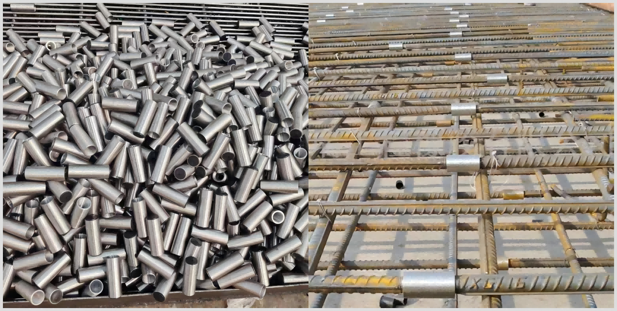
A threaded rebar coupler creates a mechanical, end-to-end connection between two bars. The load path shifts from concrete-dependent transfer to direct steel-to-steel transfer. This fundamental change guarantees structural continuity even if the surrounding concrete degrades or spalls away completely.
Mechanical splices must meet strict baseline success criteria established by international building codes. ACI 318 Type 1 and Type 2 splice requirements dictate performance in the field. Type 1 splices must develop 125% of the specified yield strength of the bar. Type 2 splices must meet the Type 1 criteria and develop the specified tensile strength of the bar. Engineers mandate Type 2 splices for high-seismic zones where plastic hinging may occur.
Alternative Methods: Why Threaded Couplers Outperform Welding and Swaging
Welded splices introduce severe metallurgical degradation. The heat-affected zone weakens the parent bar, altering its carbon equivalent value. Welding requires highly skilled labor and remains heavily weather-dependent. Rain, high humidity, or extreme cold can halt progress entirely. Furthermore, field welding requires extensive non-destructive testing, such as ultrasonic or radiographic inspection, which slows down the construction schedule.
Swaged connectors demand bulky, heavy hydraulic equipment on-site. Moving this equipment through congested work zones slows down production. The hydraulic presses require significant clearance around the bar, which is often impossible in densely packed column cages. Threaded connections offer a more agile and reliable choice. Workers can install them quickly using standard pipe wrenches or calibrated torque wrenches, ensuring consistent quality without heavy machinery.
Deep Dive: The Rib Peeling Rolling Thread Coupler Technology
Engineering Principles of Rib Peeling and Thread Rolling
The manufacturing process for a high-performance connection involves precise mechanical steps. Field operators use specialized machinery to prepare the bar ends before splicing. This preparation guarantees the thread profile matches the internal threads of the coupler perfectly.
The standard preparation sequence includes:
-
Cutting the rebar end perfectly square using an abrasive saw or cold saw to ensure full bearing contact inside the coupler.
-
Peeling the longitudinal and transverse ribs from the end of the rebar to create a smooth, uniform cylinder matching the required pitch diameter.
-
Cold-rolling the threads onto this prepared surface using hardened steel rollers. This process displaces the steel rather than cutting it away.
Cold forging work-hardens the thread profile. The root of the thread retains a cross-sectional area equal to or greater than the parent bar. This specific metallurgical advantage prevents the bar-break failures common in standard cut-thread methods. Because no material is removed during the threading phase, the connection remains stronger than the bar itself.
Evaluating the Parallel Thread Galvanized Coupler
Specific environmental applications require variations in coupler finishes. Coastal projects, wastewater treatment facilities, and chemical plants expose reinforcement to aggressive corrosive agents. Chlorides penetrate the concrete cover and attack the steel. Standard black steel couplers may degrade rapidly in these conditions, compromising the splice.
A parallel thread galvanized coupler prevents galvanic corrosion. The zinc coating acts as a sacrificial anode, corroding preferentially to protect the underlying steel. Manufacturers carefully control the hot-dip galvanizing process to maintain strict thread tolerances. They often tap the internal threads over-size before galvanizing to accommodate the zinc layer. This ensures the coating does not interfere with torque specifications during field installation.
Technical Evaluation: Performance and Structural Integrity Dimensions
Load Transfer and Tensile Strength Outcomes
Mechanical couplers consistently achieve the 125% specified yield strength of the rebar. The direct steel-to-steel connection eliminates the variables associated with concrete compressive strength. Engineers can rely on exact capacity metrics rather than empirical bond formulas. When a load is applied, the force travels straight through the coupler body, bypassing the concrete entirely.
Predictability of failure modes is a primary advantage. Destructive testing consistently shows failure occurring in the parent bar, well away from the splice zone. The connection itself remains intact, proving the mechanical splice is the strongest point in the reinforcement chain. This predictable ductility allows structural engineers to design with higher confidence factors.
|
Performance Metric |
Lap Splicing |
Mechanical Coupler |
|---|---|---|
|
Load Transfer Mechanism |
Concrete-dependent bond |
Direct steel-to-steel bearing |
|
Tensile Capacity |
Variable (depends on concrete cover) |
125% of specified yield strength |
|
Congestion Level |
High (doubles steel at splice zone) |
Low (maintains single-bar alignment) |
|
Seismic Reliability |
Low (fails if concrete spalls) |
High (maintains integrity post-spalling) |
|
Installation Speed |
Slow (requires extensive manual tying) |
Fast (simple threading and torquing) |
Seismic Performance and Cyclic Loading
Seismic events subject structures to severe cyclic loading. The building sways, rapidly alternating between tension and compression forces. Ductility and energy dissipation become critical survival factors. A rebar coupler maintains concrete-independent stability under these extreme stresses.
Lap splices often fail during earthquakes because the concrete cover spalls off, destroying the bond. Once the cover is gone, the bars simply slip past each other. Mechanical splices hold the reinforcement together even when the surrounding concrete sustains heavy damage. This prevents progressive collapse, maintains the structural frame, and ultimately saves lives during major seismic events.
Cost-to-Benefit Analysis: Overcoming the "Hidden Costs"
Material Savings vs. Component Costs
Calculating steel savings requires looking at the eliminated overlap. A standard lap splice requires 40d to 60d (bar diameters) of overlap depending on the concrete grade and bar position. For large diameter bars, this equals massive amounts of wasted steel. Eliminating these overlaps drastically reduces total steel tonnage on the project.
Consider a high-rise project using 32mm (#10) rebar. A 50d lap requires 1.6 meters of overlap per splice. If the project has 10,000 splices, that equals 16,000 meters of wasted rebar. At roughly 6.3 kg per meter, that is over 100 metric tons of steel purchased, shipped, and hoisted just for overlapping. The upfront unit cost of mechanical couplers is higher than buying plain rebar. However, comparing this unit cost against the reduced procurement of bulk steel reveals a different picture. The net material cost drops significantly when using mechanical splices on large bars.
Labor, Time, and On-Site Efficiency
Installation speed heavily favors threaded couplers. Manually tying heavy-gauge lap splices is a time-intensive, physically demanding process. Ironworkers struggle to align and secure large bars. Workers can thread and torque a mechanical splice in a fraction of the time.
This efficiency impacts the entire project schedule. Faster splicing reduces crane time for lifting rebar cages. Prefabrication becomes easier because cages can be built in modular sections and simply screwed together on-site. The overall critical path scheduling tightens, allowing formwork and concrete pouring trades to begin their work sooner.
Solving Concrete Congestion and Design Limitations
Improving Concrete Flow and Consolidation
Reducing the steel-to-concrete ratio at splice zones prevents aggregate blocking. Lap splices double the amount of steel in a given cross-section. This creates a dense net that traps large aggregates during the pour. When the aggregate blocks the flow, the cement paste separates, leading to weak zones in the structure.
Mechanical splices maintain a single-bar profile. Concrete flows smoothly through the reinforcement cage. Vibrators can easily penetrate the cage to consolidate the mix. This reduces structural defects like honeycombing and voids. Contractors spend less time and money on post-pour remediation, chipping, and patching.
Optimizing Architectural and Structural Design
Mechanical couplers relieve structural engineers from complex, variable-dependent lap length formulas. Calculations dependent on concrete grade, bar position, and epoxy coatings disappear. The design process becomes streamlined and less prone to calculation errors. Detailing the rebar drawings becomes faster and cleaner.
Engineers can utilize smaller column cross-sections. Eliminating lap splice congestion means columns do not need to be artificially enlarged just to fit the rebar and maintain clear spacing requirements. This directly increases the net lettable area. Smaller columns translate to more usable floor space and higher commercial value in high-rises. Architects gain more freedom in their floor plan layouts.
Sourcing and Implementation Risks
Selecting a Reliable Threaded Rebar Coupler Manufacturer
Vendor evaluation requires strict criteria. You must verify ISO 9001 certification to ensure consistent manufacturing processes. Demand raw material traceability for every batch of couplers. The manufacturer must provide mill test certificates for the steel used to machine the couplers. Require independent laboratory testing reports that prove compliance with local building codes, such as ICC-ES evaluation reports in the United States or CARES certification in the UK.
Avoid commoditized, low-cost alternatives. Cheap couplers often lack strict dimensional tolerances or metallurgical consistency. A poorly machined thread will strip under load. A reputable threaded rebar coupler manufacturer guarantees the structural integrity of your entire project by providing consistent, tested, and traceable products.
On-Site Execution Risks and Mitigation
Installation failures usually stem from human error rather than product failure. Improper thread rolling calibration leads to weak threads that do not engage fully with the coupler. Insufficient tightening torque prevents the connection from locking, allowing slip under load. Cross-threading damages the internal threads of the coupler and the external threads of the bar.
Mitigation requires strict field protocols. Implement mandatory operator training for the thread rolling machines. Conduct routine equipment calibration, checking the roller dies for wear. Enforce standardized torque-wrench inspections for every installed splice before the concrete pour. Inspectors should mark torqued couplers with paint to visually confirm compliance.
Conclusion
Transitioning from lap splicing to mechanical connections is a structural necessity for modern construction. Take the following steps to implement this technology on your next project:
-
Consult with structural engineers to update splice detailing for all primary load-bearing columns and beams.
-
Conduct a project-specific cost-benefit analysis comparing lap length steel waste against coupler unit costs.
-
Request technical data sheets, mill certificates, and sample testing from a vetted manufacturer.
-
Implement a mandatory on-site training program for thread rolling machine operators and ironworkers.
-
Establish a strict QA/QC protocol for torque verification and visual inspection before concrete placement.
FAQ
Q: What is the main advantage of a rib peeling rolling thread coupler over lap splicing?
A: It provides direct steel-to-steel load transfer, eliminating concrete dependency. It achieves 125% yield strength capacity, simplifies design calculations, and significantly reduces rebar congestion in columns and beams.
Q: Does using a threaded rebar coupler save money on a construction project?
A: Yes. The upfront cost of the coupler is offset by massive reductions in wasted lap-length steel and accelerated labor timelines. This often yields 20% to 50% net savings on splicing costs.
Q: Are mechanical rebar couplers approved for seismic zones?
A: Yes. Type 2 mechanical splices are specifically designed for seismic zones. They maintain structural integrity and load transfer even if the surrounding concrete spalls during an earthquake.
Q: How do you prevent corrosion in mechanical splices?
A: Use a parallel thread galvanized coupler or apply specific epoxy coatings. These finishes protect the exposed threads and the coupler body in aggressive environments like coastal regions or chemical plants.
Q: What should I look for when choosing a threaded rebar coupler manufacturer?
A: Look for third-party testing reports, strict metallurgical standards, full raw material traceability, ISO 9001 certification, and the provision of calibrated thread-rolling equipment for on-site use.
Q: Can lap splicing and mechanical couplers be used on the same project?
A: Yes. Hybrid approaches are common. Contractors often use lap splices for smaller, secondary reinforcement and mechanical couplers for primary load-bearing columns and large-diameter beams.
SHARE